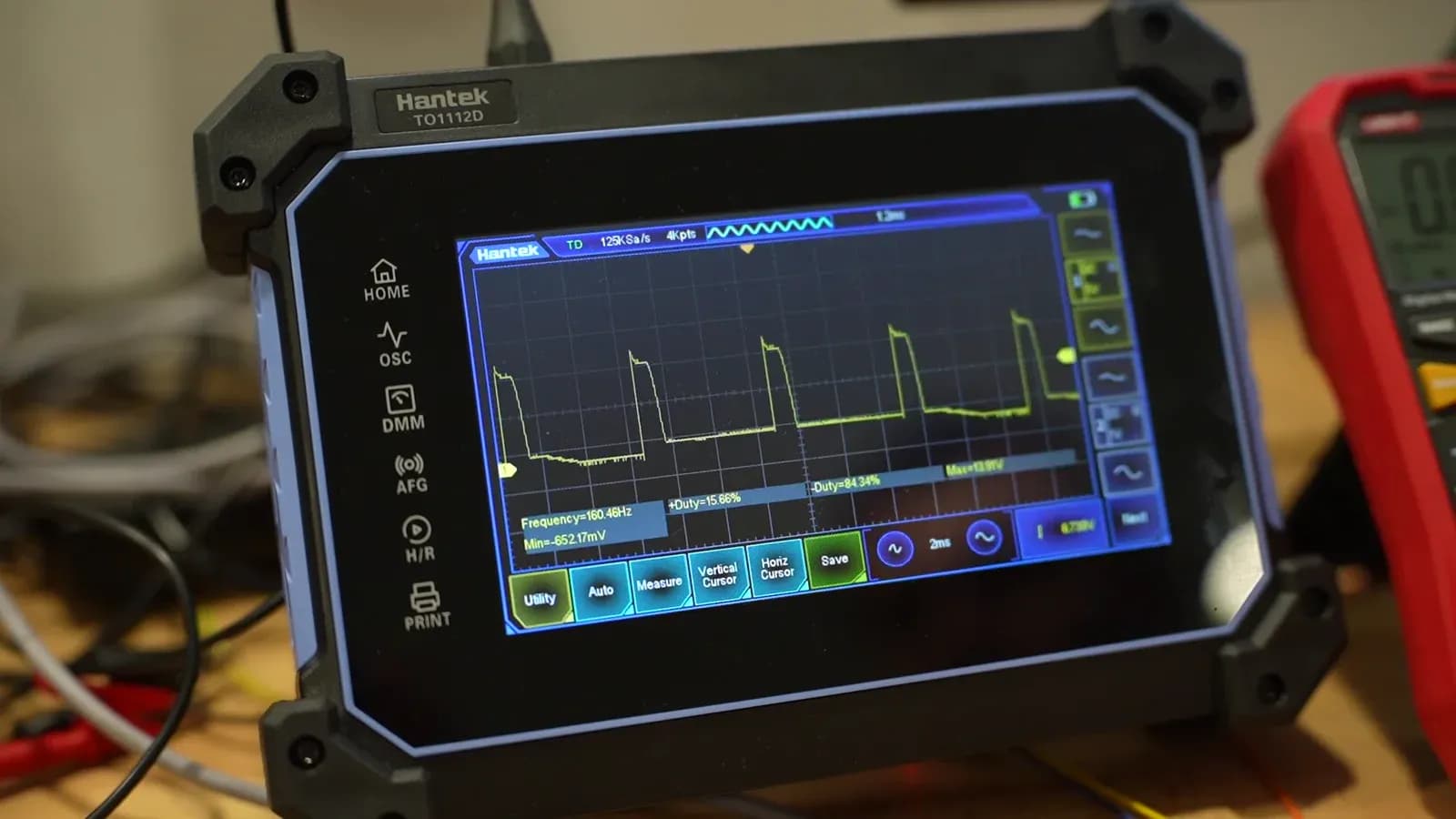
A proportional valve coil does not get a steady voltage. It gets a fast series of pulses, and the current those pulses create is what moves the spool. We put a PWM output on the bench and measured it twice: once with an oscilloscope, once with an ordinary multimeter. Every number in this article was read from the instruments during that test.
What we used: a PWM output driven by a potentiometer, a hydraulic valve coil, a Hantek TO1112D oscilloscope and a UNI-T True RMS multimeter. Supply: 12 V.
What PWM is?
PWM (pulse width modulation) means the controller switches the coil on and off very quickly instead of giving it a smooth voltage. In our test the output switched about 160 times per second: 160.46 Hz, one cycle every 6.25 ms.
The frequency stays the same. What changes is how long each pulse stays on in every cycle: the duty cycle. More on-time means more power in the coil, and the valve opens further. Turning the potentiometer changes only the duty cycle.
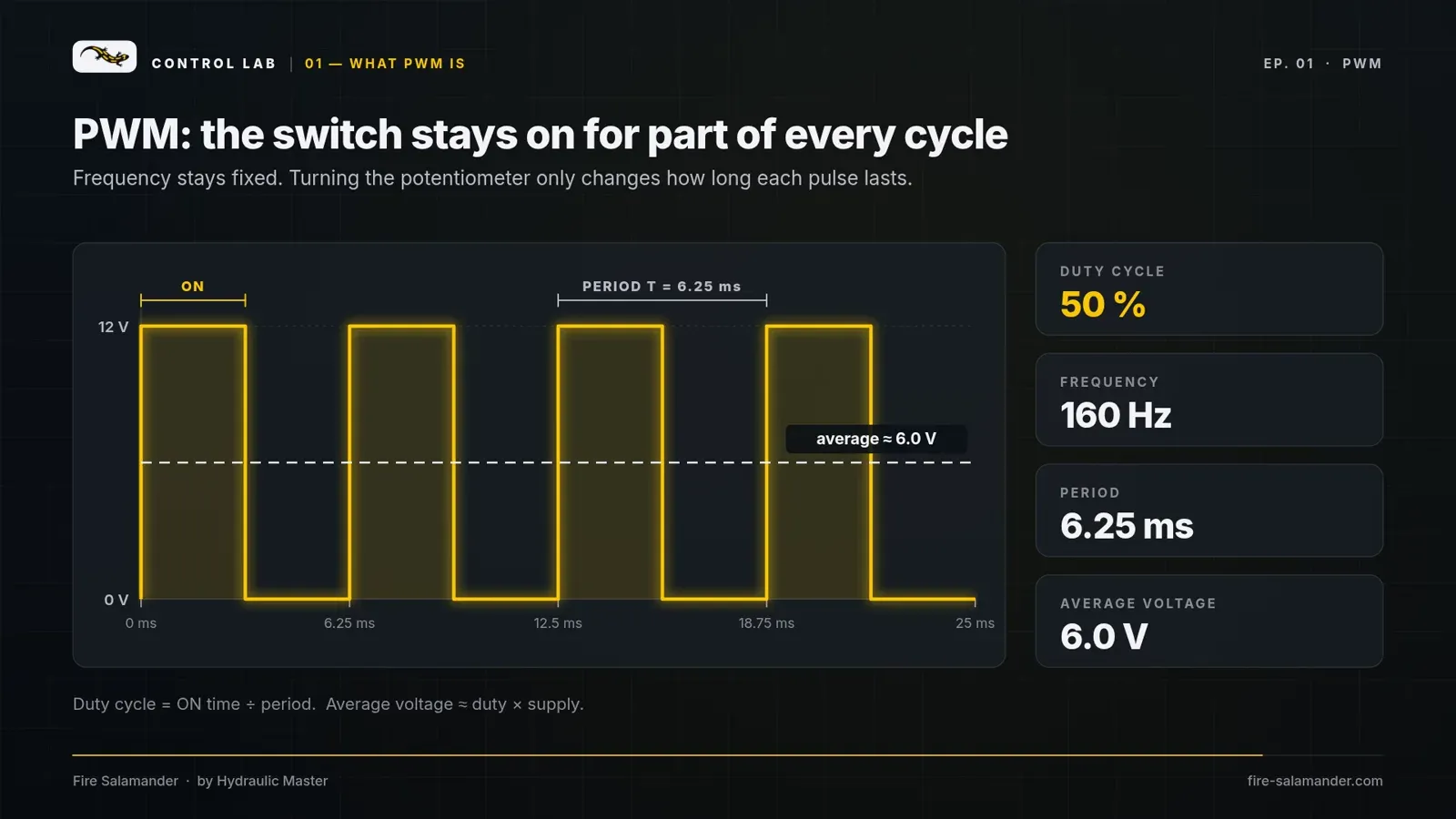
Duty cycle = on-time ÷ period.
Average voltage ≈ duty cycle × supply voltage.
A switch that is fully on or fully off wastes very little power, which is why mobile controllers drive proportional valves this way.
Connecting the oscilloscope.
The probe tip goes on the PWM output wire and the ground clip goes on minus. Nothing else is needed to see the signal.
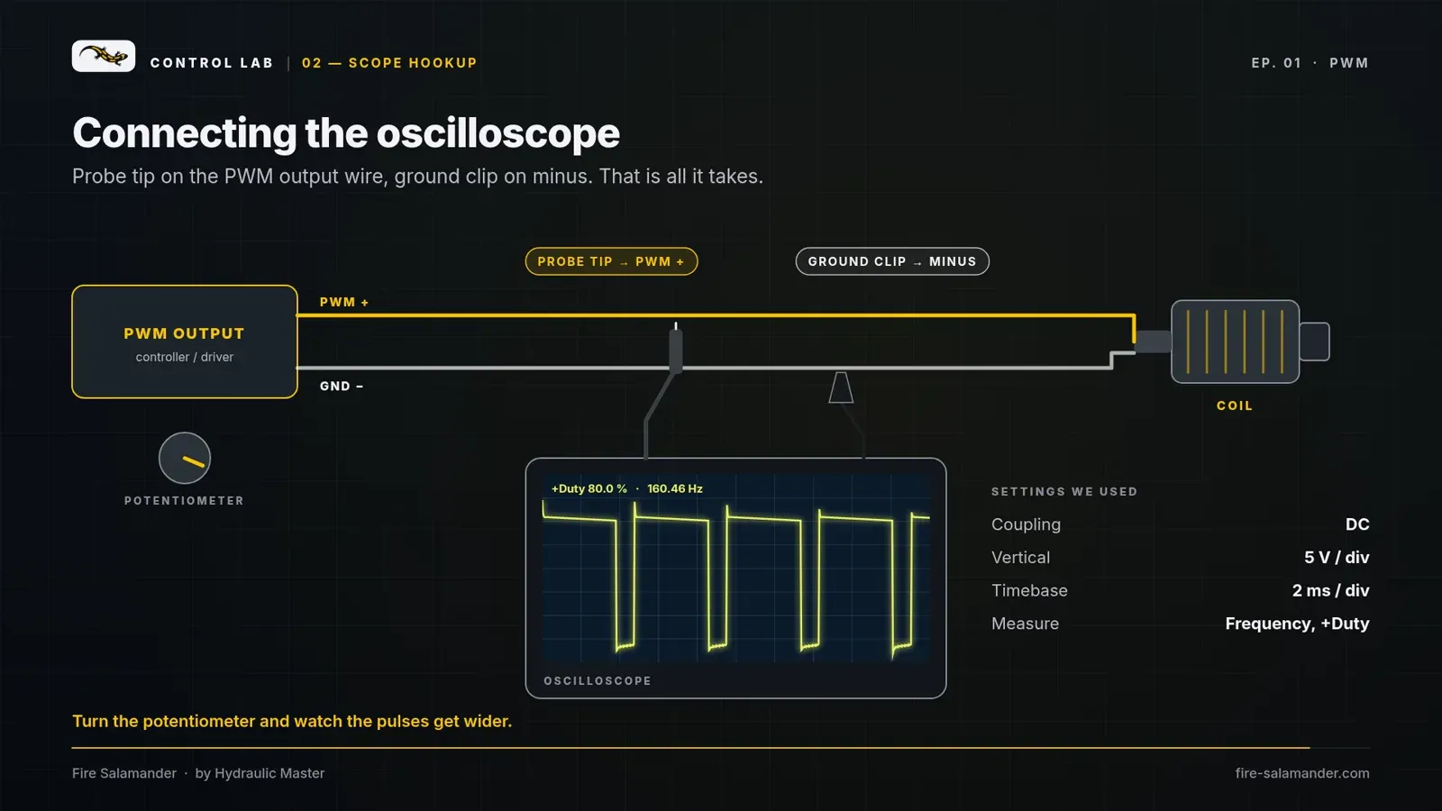
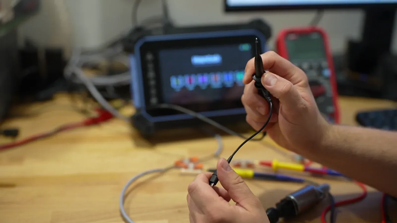
These settings put a few pulses on the screen:
Setting | Value |
|---|---|
Coupling | DC |
Vertical | 5 V / div |
Timebase | 2 ms / div |
Measurements | Frequency, +Duty |
Turning the potentiometer.
At the low end of the potentiometer the pulses are narrow: the scope measured +Duty 15.66 %. Halfway it is roughly half on, half off (about 52 %). Near the top the pulses fill most of the cycle: 80.36 %, and 86.63 % just before full output.
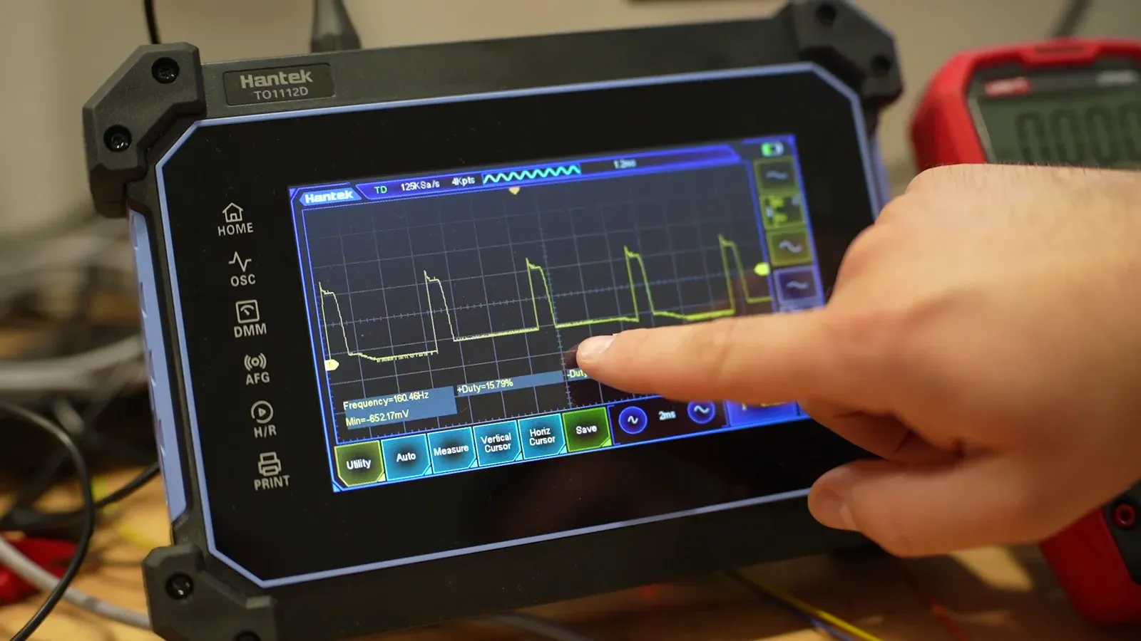
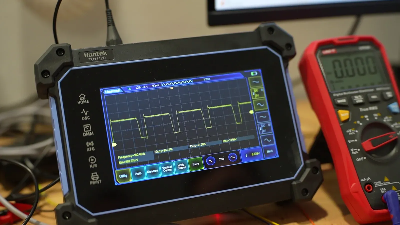
The frequency did not move at any position: 160.46 Hz the whole time. Only the pulse width changes.
Why the real signal is not a perfect square.
A textbook PWM signal is a clean square wave. On a real bench it never is, and that is normal. Three things stood out on the scope:
A spike on switch-on. Each pulse starts with a short overshoot above the supply voltage (the scope's Max reached 14.13 V on a 12 V supply). It comes from the fast edge and the inductance of the wiring.
A top that sags slightly. The supply and the wires drop a little voltage while the coil draws current.
A dip below zero at switch-off. The line falls to about −0.65 V. That is the energy stored in the coil flowing back through the freewheel diode.
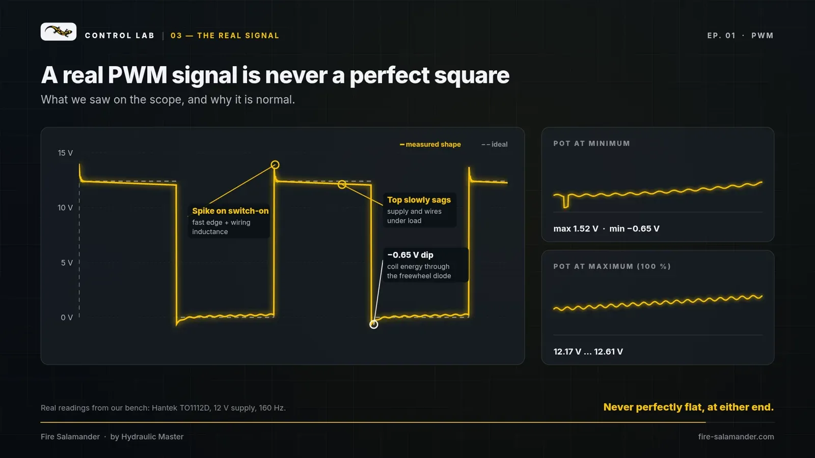
The two ends of the potentiometer tell the same story. At minimum the line is not a clean 0 V: the scope showed a small residual signal up to 1.52 V. At 100 % the line is not a flat 12 V either: it moved between 12.17 V and 12.61 V. Real wiring, a real coil and a real power supply all leave their mark.
12 V or 24 V coils?
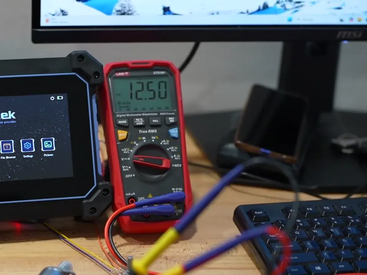
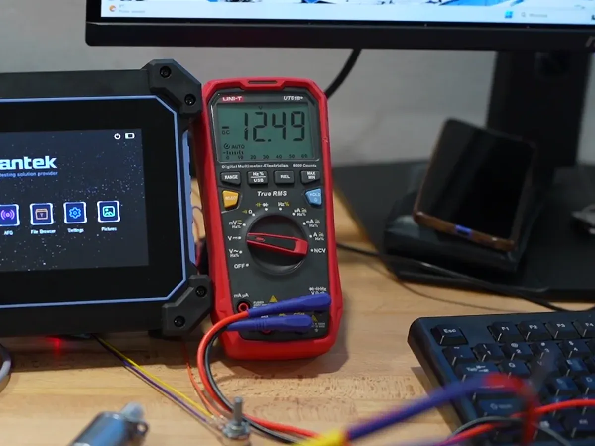
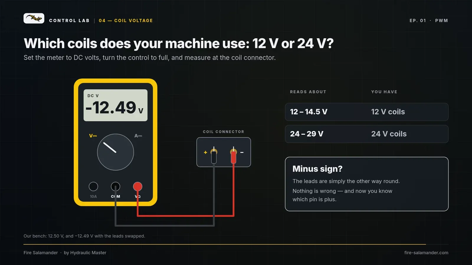
This is the first question on any machine, and a multimeter answers it. Set the meter to DC volts, turn the control to full and measure across the coil connector. We read 12.50 V, so this is a 12 V system.
Meter reads about | You have |
|---|---|
12–14.5 V | 12 V coils |
24–29 V | 24 V coils |
If the display shows a minus sign, nothing is wrong. With the leads swapped we read −12.49 V: the leads are simply the other way round. As a bonus, you now know which pin is plus.
Checking PWM frequency with a multimeter.
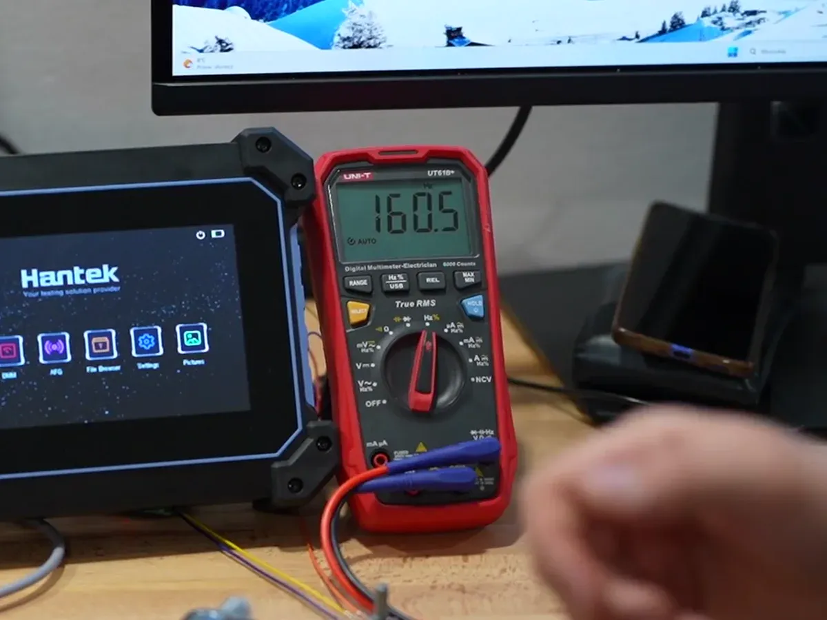
Most multimeters have a Hz function. Switch to it and measure on the same two wires. Our meter showed 160.5 Hz; the oscilloscope showed 160.46 Hz.
The meter watches the signal cross a trigger level and counts how many cycles fit into a short, precisely timed window. Cycles divided by time gives the frequency. The small difference comes from that counting:
plus or minus one cycle at the edges of the window,
noise or ringing on the edges of the pulses,
the tolerance of the meter's own clock,
rounding on the display.
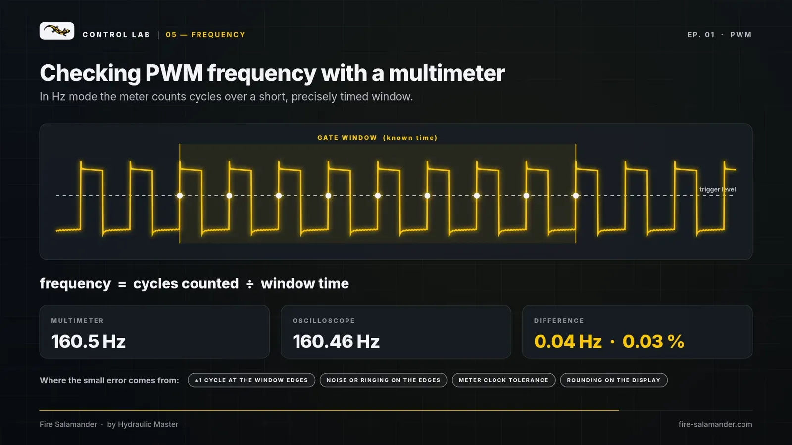
Here the difference was 0.04 Hz, about 0.03 %. That is more than good enough to know what frequency a controller runs at. To see the shape of the signal, you still need a scope.
Measuring coil current in series.
Coil current is the most useful measurement. Move the red lead to the 10 A socket and set the dial to DC amps. Open the circuit, for example at the connector, and put the meter in series so that all of the coil current flows through it.
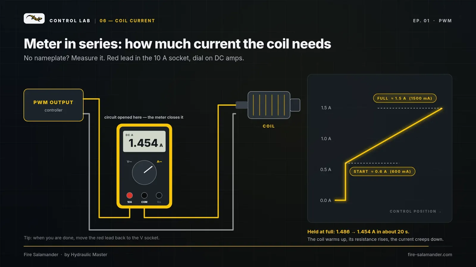
Then turn the control up slowly. In our test the coil started at about 0.60 A (600 mA). At full output we read about 1.5 A.
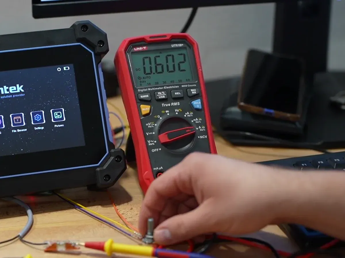
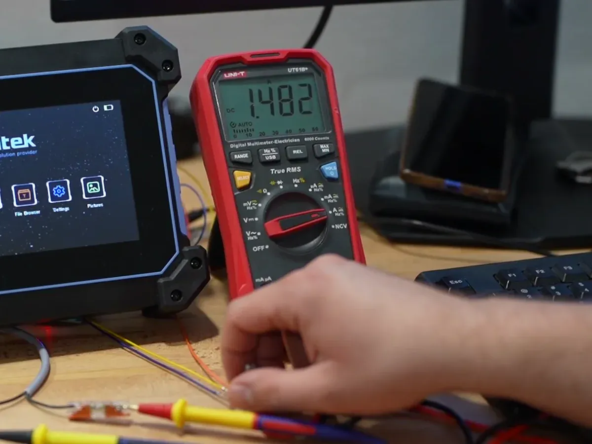
Held at full output, the reading crept down from 1.486 A to 1.454 A in about 20 seconds. The coil was warming up, its resistance rose and the current dropped a little.
No nameplate? This is how you find the current a valve needs. On the machine, with its original control, note the current where the function just starts to move and the current at full speed. Typically that is something like 600 mA at the start and up to around 1,500 mA at full. Those two numbers are what you need to set up a new controller.
Tip from the bench: when you are done, move the red lead back to the volts socket. Measuring voltage on the 10 A input will blow the meter's fuse.
What to take away.
A scope shows you the shape of the signal. A multimeter tells you the supply voltage, the PWM frequency and, most importantly, the current your coils need.
Measurement | Tool | Our result |
|---|---|---|
PWM frequency | Scope / multimeter (Hz) | 160.46 Hz / 160.5 Hz |
Duty cycle range | Scope | about 15 % to 87 % |
Dip at switch-off | Scope | −0.65 V |
Coil supply | Multimeter (DC V) | 12.50 V |
Coil current | Multimeter in series (DC A) | 0.60 A start, about 1.5 A full |
Planning a control upgrade for your machine? Send us the coil current, the voltage and a photo of the valve. We build the Fire Salamander kit around your machine and bench-test it before it ships.
FAQ
Can I measure PWM with a multimeter? Yes. In Hz mode it shows the frequency. In series on DC amps it shows the average coil current, which is the value that matters for the valve.
Why does my multimeter show a negative voltage on the coil? The leads are swapped. The reading is still correct, and it tells you which pin is plus.
How do I know if my valve coils are 12 V or 24 V? Measure DC volts across the coil connector with the control at full. About 12–14.5 V means 12 V coils, about 24–29 V means 24 V coils.
How much current does a proportional valve coil need? Measure it in series on the machine. In our test: about 0.6 A where movement starts and about 1.5 A at full output. Check your valve's datasheet when it is available.